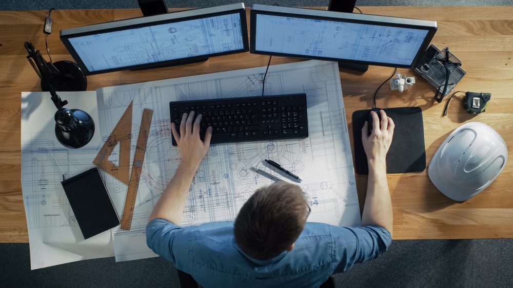
An expression with a little misunderstanding, a technical drawing, is not only an engineering subject but a skill for many fields of knowledge. Technical Drawing is an act or discipline of creating models or plans to build something through designs. It is made up of graphics communication. Drafting or draughting is also known as the visual language of industries, especially engineering, as most people say. The person who draws is called a drafter, draftsperson, or a draughtsman. To be a skilled drafter is inherent to be someone with abilities such as image perspectives, units of measurement, visual styles, layout manipulation, notation systems, and others. With these qualities, a drafter is prepared to communicate your project more concisely with a common understanding. And this is the main difference between a visual art design to a technical drawing. Artistic drawings are interpreted with a subjective vision, while a technical drawing has a direct purpose and intended meaning.
On this blog page, you will understand the history of technical drawing and how a drafter is prepared to work beside all the devices and materials he needs. Also, we will show you which market areas this professional can operate. Let’s begin.
Technical Drawing: a brief history
It is always good to remember history. As far as we know, there are many ancient marks which show us that drafting art is not a recent study.
Ancient Times:
Drafting is one of the most older documented profession. The earliest appearance of drawing was found on cave walls, next to animal hide and vellum. The ancient Chinese and Egyptian people made huge advancements by developing rice paper and papyrus. The first known city is Jericho, which is now known as the Palestinian West Bank. It’s occupation dates back to 10,000 BCE. There are a few pieces of evidence of what we would now call technical planning. Is has more than 7.000 BCE. As the civilizations became more advanced, there was a necessity to structure and organize how cities, bridges, roads, and other constructions would be built. Mathematical and measurement abilities were indeed the key to the development of this civilization. For example, we could use southern Europe and the Middle East “masterpieces” as the Coliseum, Parthenon, the Egyptian pyramids, and others.
Italian renaissance:
This incredible moment in world history has many contributions to the current drafting, designing, and engineering. Filippo Brunelleschi (1377- 1446) started the flat representation of objects in three dimensions and became one of the most influential architects of Renaissance aesthetics. Rafael Sanzio (1483-1520), an Italian painter and architect, spent his life residing in Florence, considered to be the birthplace of the Renaissance. He was a Master of Painting and Architecture at the city’s School of Arts. He was chosen to be the architect of the new St. Peter’s Basilica in Rome, and through his studies on preservation, he made an archaeological map of the city. The greatest Sanzio’s contribution to the technical drawing was, along with Felippo, the representation of a three-dimensional perspective. He was capable of translating the 2D image that the eyes create into the three-dimensional image that the brain interprets onto paper. Although best known as the Mona Lisa painter, Leonardo da Vinci (1452–1519) exhibited numerous skills in the sciences and engineering creations. As a scientist, Leonardo had no formal study in Latin and mathematics and did not frequent a university. Because of these circumstances, his scientific studies were ignored by other scholars. Leonardo’s approach to science was one of intense observation and detailed recording. His research tools being almost exclusively his eyes. Their diaries give tips on their investigative processes. He kept a series of notebooks he wrote almost daily, as well as separate notes and blocks of observations, comments, and plans. Many documents have survived to illustrate their studies, discoveries, and inventions. In Leonardo’s notebooks, there are many war machines, such as a vehicle propelled by two men through crankshafts. Also, there were flying machine designs and bridges projects.

Thus, we can admit that the “dark ages” has lighted up the technical drawing study. Nowadays, it is a little difficult to imagine how they did these work by hand-made production, using drawing instruments, which were early versions of the ruler, set square, compass, and protractor.
First Industrial Revolution:
This revolution era received lots of innovations, tools, structures, multiples states materials, and the beginnings of mass production. The origin of new machines and mass manufactures products required improvement in the drawing techniques. During this time, engineering and drafting take place in the market, especially in the textile industries.
Second Industrial Revolution:
Between 1900 and 1945, industrial production of products for both the military and the emerging consumer class and greatly intensified. Not only was the number of products being produced rapidly growing, but becoming increasingly complex. Designers needed to more accurately portray the working mechanical elements of increasingly complex systems of machinery. During this period, how technical drawings were draw began to become standardized.
After World War II:
After this historical world war, the demand for customer goods increased. Science. At the same time, the space race helped create a global focus on science and technology. This innovation required the development of millions of technical drawings, but for engineers and drafters, everything had changed in the 1960s, with CAD origin. Dr. Patrick Hanratty imagined the first numerical control system, which later becomes Computer-Aided Design or CAD. The preciseness, skillfulness, and edit-ability of CAD designs revolutionize the engineering, architecture, and manufacturing landscape. But what is CAD, after all? CAD, or Computer-aided design, is a digital technology that creates two-dimensional or three-dimensional diagrams, which can be observed from any point of view, even from the inside looking out. The term “computer-aided design” was invented by Douglas Taylor Ross, an American computer science pioneer and considered the father of Automatically Programmed Tools, a language to drive numerically controlled manufacturing. CAD can assist in the manufacturing process by associating all issues involving the complexity of a given material (such as strategies, tolerances, and measurements) with the specific conventions for the merchandise in question. This was a revolution for technical Drawing because now all the analogic tools could be replaced for the digital design. However, in 1960, Computer-Aided Design software and computer had been developed, but each machine costs millions of dollars. Only large companies had conditions to buy it, such as the military, NASA, or car companies could afford these systems. Only two decades later, with the “internet bubble.” personal computers became something more ordinary, also CAD.
Drafting Tools
It may be used for the determination and layout of drawings or to improve the consistency and speed creation of standard drawing elements. Tools such as pens and pencils mark the drawing medium. Straight edges, assist the operator in drawing straight lines. Various scales are used to measure the lengths of lines and angles, allowing an accurate drawing to be carried out. The compass is used to draw curves and circles. A drawing board was used to place the drawing chart. Tools such as templates and lettering guides assisted in the drawing of repeated elements like circles, ellipses, schematic symbols, and text. The tools used for manual technical drawing have been displaced by the advent of computer-aided drawing design (CADD).
Essential skills and abilities
You need to develop some skills if you want to be a drafter (as our ancient masters and current engineers). We separate some to inform you.
Drawing Perspectives
As we talk about our ancient architects and engineer’s contributions (on their time), we must detail the drawing perspective types they help us to develop and improve. Perspective drawing is looked on as a complicated issue sometimes but is the fun side of painting instead. To sum up is a technique to create the linear illusion of depth to our eyes. As the object gets distant from the viewer, they appear to decrease in size at a constant rate. To put this technique on paper, there some linear perspective methods.
One-Point Perspective (or central perspective): Contains only one vanishing point on the horizon line positioned somewhere inside the picture plane, and all the orthogonal converge towards it. It allows creating a focal point to pay attention and develop the rest of the drawing.

Two-Point Perspective (or angular perspective): It has two vanishing points on the horizon line, spread across the picture plane, mostly used when you see two perpendicular sides of an object, both distorted. The funny thing about this perspective is utilizing a vertical line instead. With a little twist, we can use the vertical line to simulate the dynamics of a 3-point perspective with two vanishing points.

Three-Point Perspective: uses three vanishing points in a way to make a triangle (two points on the horizon line a one above or below). This technique offers a dynamic view, gaining a real 3D perspective.

Multipoint Perspective: it contains more than two vanishing points on the horizon line. It is the most approach image of a real-world scene.
Units of measurement
It is essential for a draftsperson scales up or down a project to have a clear view. One of the objectives of technical drawing is scaling, so a professional like an engineer or builder has the exact specifications to execute it. When examining scales, the number on the left equals the measurement on the drawing; the number on the right is the actual size like the example below.
Architect’s scales: This professional has many projects. It could be big like a building or a structure design, or something smaller, as seen on interior design (doors, windows, floors, and walls). It uses the “inch” with a particular reading form, always converting. Inches into feet. Example: 1 foot 0 inches. The scale 1/8 inch = 1 foot 0 inches means that 1/8 inch in the drawing equals 1 foot in the actual building.
Civil engineer’s scales: A civil engineer has an incredible job of sketching large and complex projects of roads, water mains, bridges, etc. The scale “inch” is often used in these works. By definition, an inch is a unit of linear measure equal to one-twelfth of a foot (2.54 cm). However, to scale a project an easier way, 1 inch can represent 100 feet in real life. This is because an inch can be divided into equal decimal units of 10 to 80. An example: 1 inch = 10 feet, 1 inch = 100 feet. The 20 scale is used for scales such as 1 inch = 2 feet, 1 inch = 20 feet and 1 inch = 200 feet. It does not matter how many feet you are applying, transforming for inches, the values increase by multiples of 10. We cannot forget that all these units and dimensions have a standardizing. Any kind of building and engineering work must apply the appropriate measurement form. It must respect some institutional rules, grounded by:
The American National Standards Institute (ANSI): a private organization that manages the development of spontaneous agreement standards for products, services, processes, systems, and personnel in the United States. The organization also organizes U.S. criteria with international standards so that American products can be used worldwide.
The International Standards Organization (ISO): is an international standard-setting body composed of representatives from various national standards organizations. It is the world’s largest developer of voluntary international standards, and it promotes world trade by providing common standards among nations.
Technical drawing courses
Are you interested in drafting? Many students do some courses to develop formal knowledge into a technical drawing. In some colleges, extra-courses can be utilized to earn credits for a bachelor’s degree in architecture, engineering (mechanical, electrical, civil, etc.). But what you will learn in a drafting course? First of all, you will discover a precise and practical approach to measure and calculation. Then, you will be prepared to visualize and design low-difficult blueprints (initially by hands and later with an assist of 2D and 3D CAD software). Courses are often available at colleges and universities around the world. Some courses are offered by local organizations or can be taken online.
Modern Techniques
In today’s technology-driven industry environment, most technical drawings can be made by computer. Though many businesses may still work by hand drawing, computer software is the primary medium used today. Programs that perform technical drawing functions include AutoCad, Solidface, SketchUp, Microstation, CorelDraw, Vector works, or Adobe Illustrator. The principal benefit of these programs is that a drawing can be flipped, turned, and rotated as the user desire, all by a click of a mouse. This enables a single illustration to be viewed from numerous angles. If you are working with additive manufacturing, you probably will need a 3D printer to work in association with CAD.
Technical Drawing Jobs
Several career paths are available in technical drawing, including mechanical, architectural, and electrical drafters. Graduation from a technical school or a degree in a relevant field is required to work in technical drawing. Drafting professionals use hand drawing techniques as well as 2D or 3D CAD software to make drawings for everything from tiny bottles to skyscrapers. There must be a balance between artistic talent and mechanical ability and, of course, demonstrate expertise with computers and design/modeling software. Some fields, for example, might also demand knowledge of math and physics. Drafters produce drawings and plans for a wide range of areas. Their sketches provide visual support and blueprints for construction and factory workers, engineers, and architects. Next, we separate some jobs, their activities, and an estimated salary.
Architects: work in the housing or construction industry, composing drawings for architects, or adding details to existing blueprints. They may be required to draft plans for houses and other buildings or renovate existing structures. Also, they translate physical blueprints and sketches to electronic versions to show a digital representation to their clients with the proposed projects. Professionals in this field must know building techniques. According to the U.S. Bureau of Labor Statistics, architects receive a median annual wage of $76,930 per year ($36.99 per hour).
Engineers: can develop projects in different áreas, each one with your respective formation and degree. An engineer could design electrical, civil, computer hardware, petroleum, aerospace, chemical, and other labor drawings. However, each área has a distinctive salary. We separate some of them, from entry-level to experienced payroll:
- Aerospace Engineer: from $65,450 to $103,720.
- Chemical Engineer: from $58,830 to $154,840.
- Computer Engineer: from $63,970 to $150,130.
- Eletrical Engineer: from $57,330 to $89,180.
- Materials Engineer: from $52,900 to $85,150.
- Petroleum Engineer: from $74,240 to $186,520.
CAD application on technical drawing
Reuniting all the previous skills with technology, it all converges to one point: computer-aided design knowledge. What CAD stands for? Computer-Aided Design can be a powerful ally for many technical drafters. The CAD may facilitate the technical drawing procedure by adjusting complex diagrams with the materials, strategies, tolerances, and measurements utilized. CAD software is now used by designers, engineers, researchers, and many other professionals. This is why software manufacturers are changing and enhancing features. As new developments are appearing, we have started to see the form of the continuing future of CAD software.
Some CAD options
We also separate some choices for you, even if you are an entry-level drafter or a skilled professional – the best of it: all FREE options.
SolidFace: We consider it the best existing AutoCAD free option. SolidFace is a 2D/3D parametric constructive CAD modeling software. It has some advantages like the 2D and 3D simultaneous creation for mechanical pieces, multiple engineering diagrams, graphic design in general, civil plants, etc.
SketchUp: Its a free program easy to use and grasp. It is a quite good software for beginners, who are learning CAD basics and starting to execute their first designs. That is why it is trendy among users from different areas of the industry, besides architecture, construction, design, and drawing (regardless it covers these fields), such as video games and movie designs.
Using SolidFace on technical drawing
If you are looking for a complete CAD – Download SolidFace for Free.
The SolidFace 3D CAD lets you open and edits a drawing in a few seconds. Also, ensure the opportunity to give and write annotations within the drawing. It is insane how easier you can manipulate your technical drawing. Detailing the framework is especially helpful if you need to make short edits to drawings of large arrangements or drawings with various sheets, configurations, measurements, or resource-intensive sights. We develop a much more agile way of designing complex drawings by enabling you to edit your assembly. To review, the SolidFace 3D is the fastest way to present, look, measure, and now publish your project inside Solidface. Do it without needing to do an upfront job, such as create configurations or use various other techniques. You can use your sketch without needing to bring up all of the complex component information; it offers just the info you would have to view, measure, and edit the assembly-making quickly.
Check it out some advantages of Solidface:
Free tutorials: You don’t need to be searching for forums, reviews, and pages to discover how to do what you want to do. Keep it simple with SolidFace. We have a lot of free tutorials for you to learn and become an expert CAD drafter.
Free Updates: We know software updates could be very frustrating. Much valuable time being spent with loadings or even, you need to pay an extra to have that actualization. Don’t worry. We took care of it.
Complete 3D Part & Assembly Modeling: create complex structured and detailed assemblies with built-in standard hardware and parts from other Documents and libraries. Employ top-down drawing design and assembly motion. Create simulation and much more.
Share Technical Drawing ideas. Learn more!
One of the foremost goals with this 3D builder was to be fun for all ages, from engineering students to experienced professionals. So, our team desired to share our passion and energy for SolidFace along with our community. Our objective is to build a creative and unified space to learn and enjoy. We know many companies have difficulty in promoting communication and community sense. We have the aim to create a grouped community on the platform for several users to join, allowing collaboration between regions. Everyone will be ready to start using it as a way to join and communicate.

