There are many reasons why solid modeling plays an essential role in the manufacturing process
. Solid modeling makes 3D design easy by automating difficult engineering calculations that would be inconvenient and time-consuming to do manually. Manufacturers can use solid modeling to produce better results because solid modeling ensures that the measurements of the concept are accurate in relation to the design software.
What is solid modeling used for? Solid modeling is used to create 3D objects that have geometrically correct surfaces. Solid modeling simulates 3D concepts from within and without and can automate precise mathematical calculations.
Many industries use solid modeling to create highly accurate concepts for machines and parts. Solid modeling is a tool that helps manufacturers to plan and verify prototypes that will be used in the machining or assembly process. Solid modeling is not only used by engineers either as interior designers, printing and media companies, and video games and movie creators and various other industries have started relying on CAD technology.
What Exactly Is Solid Modeling?
Essentially solid modeling is the practice of modeling 3D objects using computer-aided design software like Solidface. Solid modeling is used by professionals when they want to create representations of the solid parts of an object on their computers. Solid modeling is very important because of its ability to produce 3D models and concepts that are mathematically accurate.
Usually, the model consists of wireframes that present the object in the form of a wire mesh. This model that is constructed from wireframes can be 2D, 2.5D or 3D. The object is given a solid appearance by applying surface representations to the 3D wireframes of the model in different views.
Solid modeling is often seen as the cornerstone of CAD and there is more to this technique than what meets the eye. Computer analysis and rapid prototyping that is used with 3D printing is made possible with the details that are provided by accurate solid models.
Many CAD professionals use solid modeling as it is an extremely powerful tool for creating 3D representations of concepts and drawings. With solid modeling, a 2D drawing is transformed into a 3D electronic representation showing every aspect of the object. 3D objects that are created with solid modeling techniques can be sectioned to show their inner structures or rotated and spun in any direction on the screen.
Wireframe modeling, surface modeling, and solid modeling are all 3D modeling approaches that are frequently used by CAD professionals. Because each modeling technique has basic operations that define it, wireframe and surface modeling are quite similar to solid modeling.
The first technique that was used to create 3D models on computers was wireframe modeling. Wireframe modelings enable us to create 3D representations by identifying all of an object’s edges and vertices with a wired mesh. Even though this is one of the older ways to create 3D objects on a computer, the technique is still relevant today.
Specializing in flexible capabilities to define surface geometry, surface modeling gives 3D objects a much more solid appearance. This technique is frequently used to engineer freeform surfaces with CAD software.
Solid modeling can work with wireframe and surface modeling techniques. However, most of the time 3D operations that show mathematical operations or software objects are used to create solid models. Extrusion (a method for pulling 3D objects from 2D drawings) is an example of this.
Digital prototyping is made possible because solid models enable us to describe objects in precise detail. This enables manufacturers to check all of the specifications of a part including how strong it is, how fluids and heat will affect it, and how it performs with other parts. Due to solid modeling being so accurate, all of the aspects of a specific part can be seen before it is ever produced or manufactured.
Manufacturers can see an object as it would be even before it was produced. Some real-life solid modeling applications include testing how airplane parts will react under pressure or automobile crash tests. With solid modeling, professionals can identify the weak points in their designs and improve all aspects of a manufacturing part or product.
Mathematical Foundations Of Solid Modeling
The need for Informational completeness in mechanical and geometric modeling systems is what solid modeling relies on. There is a great demand for CAD software to be able to support all geometric queries that may be asked of the physical object that it correlates with. The requirement is that the software can generate many different representations of the same object while still being consistent.
Unless the notion of a physical object can be defined with computational and mathematical properties, it would be impossible to computationally verify the accuracy of the measurements contained within the solid model. For this reason, mathematical standards have been developed that have shaped the way that we create solid models today.
CAD software makes it easy for professionals to apply mathematical accuracy to their solid models. This can help engineers get extremely realistic results and also help them to find weak points of a model before starting the manufacturing process.
What are the advantages of solid modeling?
Aside from enabling manufacturers to view a product as it will be before it is produced, there are many other benefits to using solid modeling. Solid modeling has revolutionized how we create and manufacture products, concepts, and media. For this reason, many industries have come to rely on CAD software to create realistic and accurate models.
Because solid models are created in digital format, it is also easy to share and distribute work online. This enables people to share, re-use and download models or even publish them to websites. An assembly of custom or standard parts can be created by modifying existing models.
Because the models are created using CAD software, it is very easy to print them out. This can be extremely useful for creating professional high-quality presentations that will be shown to clients or investors. The ability to print out or share solid models makes it easier for professionals to distribute and give examples of their work.
More About Solid Modeling and Computer-Aided Manufacturing
Solid modeling is frequently used by industries for computer-aided manufacturing. Solid modeling helps professionals to bring their ideas to life in the form of computer-aided models with the help of CAD software. When CAD software is used to create tools and parts related to the manufacturing of workpieces, it is also known as computer-aided machining.
Almost any physical object or product in the real world can be simulated in the form of a solid model. Computer-aided manufacturing has played an important role in the manufacturing of trains, airplanes, and cars. Whether designing an aerodynamic wing, or a high-performance engine, CAD software has made it possible to create concepts and designs that are extremely accurate and precise.
Because computer-aided manufacturing relies heavily on software and computer-controlled machinery during the manufacturing process, its success is based on three critical components. The three essential components of computer-aided manufacturing are software, machinery, and post-processing. Manufacturers have spent years fine-tuning the production process and this has resulted in the creation of some of the best manufacturing systems imaginable.
CAD software and other software generate tool paths that tell machines how to make products. The machines convert raw materials into finished products and post-processing convert tool paths into a language that machines can understand. These three components make up the core of computer-aided manufacturing systems.
Without computer-aided manufacturing, there would be no need for CAD software and solid model designs. CAD mainly focuses on creating and designing solid models of a product. Solid models help us to see what the end result will look like, and how a product will function.
CAD software and computer-aided manufacturing systems rely on each other to be successful. Even if you created the best solid model of a tool or machine part, it won’t mean much if you can’t manufacture the product. For this reason, computer-aided manufacturing systems need to be able to convert your solid models into actual products.
Every engineering process starts with the concepts being designed in CAD. Engineers will draft up 2D and 3D drawings along with solid models. This can be anything from a circuit board to a crankshaft for an automobile.
When the solid model has been completed with precise specifications, it can then be loaded into computer-aided manufacturing systems. This is usually done by exporting the CAD file so that it can be imported into CAM software. For this reason, it is important that the specifications of your solid model are engineered to be mathematically accurate.
After importing the solid model into CAM, the software starts getting the model ready for the machining process. During this process, raw materials will be converted into a final product through the process of fusing, cutting, boring, and drilling. There are several actions involved with preparing a model to be machined using CAM software.
First, the model is checked for geometrical errors. This is important as any geometrical errors will impact the manufacturing process. If geometry errors are found in the model the specifications are revised to bring about more accurate measurements.
The next part of preparing the model consists of creating a toolpath. A toolpath is a set of coordinates that the machine must follow during the machining process. Without the toolpath, the machine will not know which actions to take when converting the raw materials.
It is also important for the machine to know which parameters to use during the manufacturing process. This involves setting the cutting speed and angles, voltage, and other specifications. Great care should be taken when setting up the parameters to ensure the best quality products.
The final step involves setting up the CAM system to judge the best orientation for parts that will maximize machining efficiency. This set of actions make up most of the preparation work that is needed for a model to undergo the machining process.
The information gets sent to the machine to physically produce the part as soon as the model has been prepared for machining. The machine knows what to do because the instructions have been converted to a language that it understands. This language is known as G-code and controls the machine’s processes like feed rate, speed, coolant, and more.
The machine does most of the work once the G-code is loaded and the operator has started the manufacturing process. Computer-aided manufacturing is about building really great parts by bringing people, processes, machines, and software together. Producing high-quality parts for automobiles, trains and other sectors of industry is easier than ever before.
In earlier years large companies of the automotive and aerospace manufacturing industries made use of commercial applications of computer-aided manufacturing. Since that time CAD software has improved and overcome many of its shortcomings which has reduced the need for skilled CNC machinists. Now solid modeling techniques are frequently used by high production or high precision manufacturers.
Some of the major historical shortcomings in computer-aided manufacturing that is constantly being improved by CAD software include ease of usage, manufacturing complexity, and integration with PLM and extended enterprise.
Because CAD software is becoming easier to use, more people can take advantage of templates, libraries, and other features that the software offers. This helps improve confidence when constructing solid models and also quickens the learning curve. 3D visualization has become easier with closer integration of the CAD environment further boosting user confidence.
In the past, the manufacturing environment was very complex. Modern CAM systems have made the manufacturing process a lot smoother as better support for tools has been introduced. Because tool paths, feed rates, tool life, surface finish, and cutting depth has been improved, high-quality products can be rolled out at a faster rate.
Because modern CAM systems have become scalable to fully integrated multi-CAD 3D solution sets, the needs of manufacturing professionals have been met more accurately. This is especially true in regard to part planning, shop documentation, resource management, and data management.
CNC Machines Used to Manufacture Solid Models
The kind of machines and raw materials that you will use to manufacture your product will largely depend on the relevant sector of the industry. If you were engineering automobile parts you may use a very specific set of raw materials and machines to manufacture your model. CNC machines are machine tools that are controlled via a computer.
CNC is short for computer numerical control and basically means that machine tools are controlled with the help of a computer. In the earlier years, machine tools were operated by machinists. Technology and computer software have revolutionized the manufacturing process and now machine tools are more similar to robots that automate the machining process.
There are many different kinds of CNC machines available to manufacturers today. The kind of CNC machine that you will use will depend on the type of product that you are trying to manufacture. 3D printers, CNC mills, CNC lathes, CNC lasers, and CNC routers are all examples of machines that are used in the machining process.
CNC machines have enhanced the efficiency and speed at which products can be manufactured. Once your solid model has been accurately designed, it is easy and convenient to sit back and let the computer do all of the work of cutting, fusing, drilling and more. Manufacturers opt for using these robots because they boost productivity and can run automatically without needing to be constantly operated.
CNC Routers
CNC routers are quite similar to CNC mills and use high-speed spinning components to cut out a variety of shapes. CNC routers are often used in wood manufacturing plants to cut out parts for filing cabinets or to engrave designs on wooden doors. These machines are able to move along an X, Y, and Z-axis which makes it possible to cut precisely at many different angles.
CNC Milling Machines
CNC milling machines utilize a rotating spindle with a cutter placed inside. Chips are sliced off as the workpiece is moved past the cutter and this is commonly referred to as milling. Modern-day CNC milling machines are very precise and are able to cut objects in 3D.
CNC Lathes
CNC lathes work by spinning the workpiece in a spindle while a fixed cutting tool does the slicing. There is a wide variety of CNC lathes that are used for manufacturing products. When a workpiece is cut on a CNC lathe it is known as turning.
CNC Water, Plasma and Laser Cutters
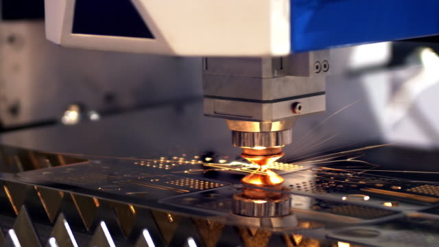
Equipped with precise lasers, high-pressure water, or plasma cutters, these machines can perform controlled cuts or engravings. These machines are highly efficient and can do large scale engraving work in just a few hours. CNC plasma cutters are frequently used to cut through different kinds of metals and other highly conductive materials.
CNC Electrical Discharge Machines
By using an electrical discharge these machines cut raw materials and help to convert them into finished products. With temperatures reaching higher than 12000 degrees celsius the spark is created between an electrode and the raw material. Electrical discharge machines are extremely precise and can melt through a variety of raw materials.
3D Printers
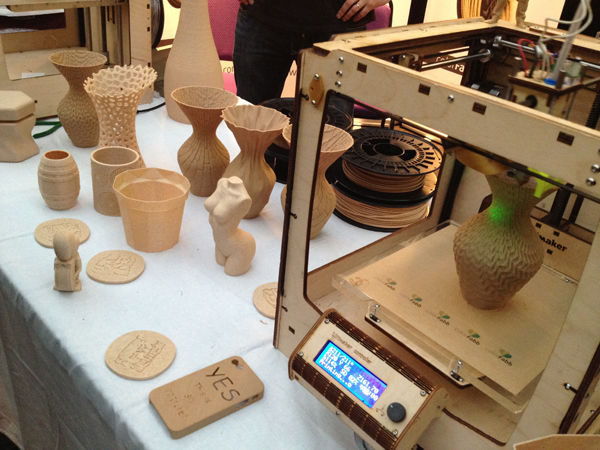
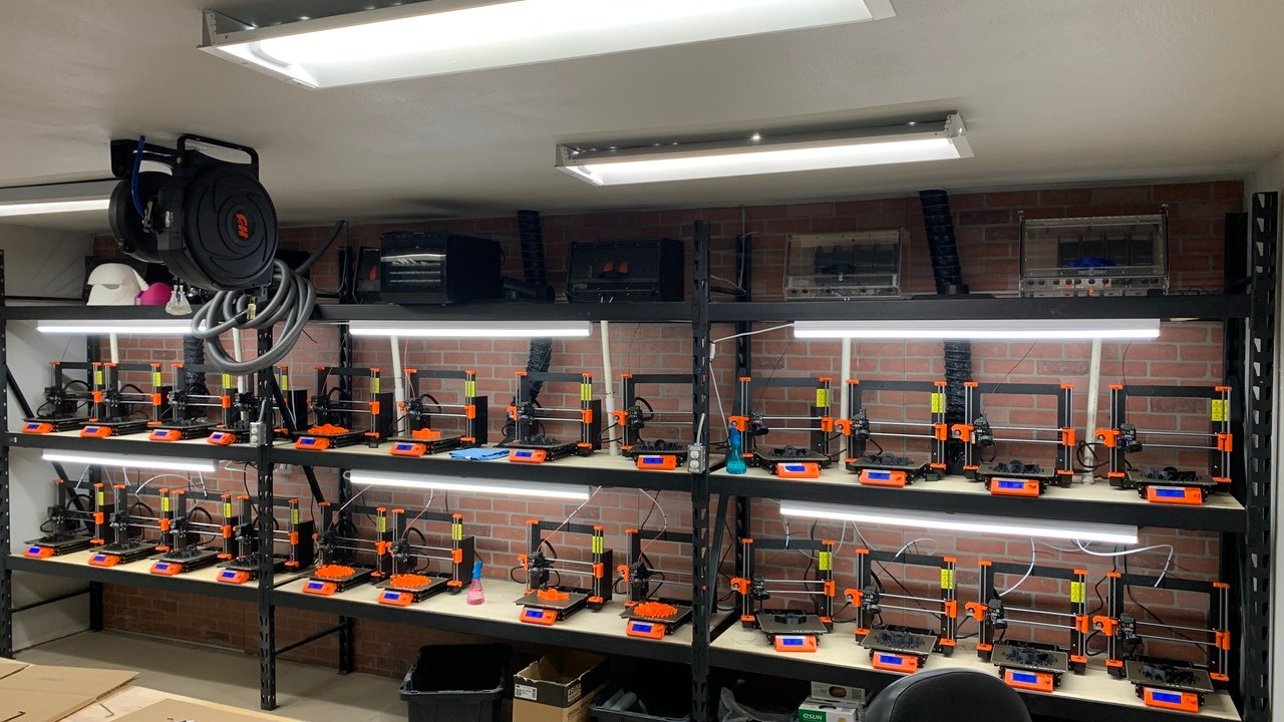
3D printers have a variety of different uses and applications when it comes to manufacturing. Some 3D printers have been used to manufacture small plastic models, while others have been used to produce in large scale construction projects to produce buildings. These machines are extremely versatile and have a large number of applications across industries.
Related Questions
What is digital prototyping used for?
Digital prototyping is used by industrial designers, manufacturers, and engineers to design and visualize their products throughout the product development process. Because of its ability to enable manufacturers to explore a complete product idea before ever being produced it has revolutionized the engineering industry.
By giving teams the ability to assess how moving parts work, digital prototyping is more than just creating designs in 3D. By using digital prototyping, professionals can determine how likely a product is to succeed or fail and see how the various components will interact with each other. This helps manufacturers to reduce the number of physical prototypes that have to be created before a product is manufactured, which reduces production costs dramatically.
What is geometric modeling?
Geometric modeling plays an important role in creating realistic prototypes for the production of products. CAD software allows for computational geometry and mathematics to be applied to 3D models. This makes it possible for professionals to get results that are extremely realistic and precise when creating solid models.
Geometric models also play a vital role in the creation of 3D concepts and plans that are used for manufacturing products. Some industries that frequently employ the use of geometric models include civil engineering, mechanical engineering, architecture, and other technical fields.


